One Shot 555 Timer Schematic : How to Build a 555 Timer Monostable Circuit - Sep 29, 2015 · monostable multivibrator (mmv) mode of 555 timer ic is also called single shot mode.
One Shot 555 Timer Schematic : How to Build a 555 Timer Monostable Circuit - Sep 29, 2015 · monostable multivibrator (mmv) mode of 555 timer ic is also called single shot mode.. Jun 02, 2021 · arduino. As the name indicates, only one state is stable and the other one is called unstable or quasi stable state. The 555 timer is not well suited for this application but it is one that is in wide use with model railroaders. Ascii characters only (characters found on a standard us keyboard); Need help arduino dc motor
Sep 29, 2015 · monostable multivibrator (mmv) mode of 555 timer ic is also called single shot mode. Other circuits include a combination lock for a computer, or a game in which players compete to be the first to press a button. Shown on the schematic is a secondary output that uses the open collector at the discharge input (pin 7) of the timer. I need a software to make hpma 1150 sensor work in arduino mega 2560. The 555 timer is not well suited for this application but it is one that is in wide use with model railroaders.
555 timer monostable mode or one shot explanation and ... from i.pinimg.com The 555 timer is not well suited for this application but it is one that is in wide use with model railroaders. Build your own oscillator and one shot circuits, and learn how to chain timer chips together. Need help arduino dc motor Jul 25, 2021 · the 555 timer is configured as a missing pulse detector meaning that if it does not detect the pulse that originated upstream at the 6821 pia at 11b, the output of the 555 timer at pin 3 (and 7) will go low, which invokes blanking and protection of the system circuitry. 555 timer is a digital monolithic integrated circuit (ic) which may be used as a clock generator. A simple circuit can test the speed of your reflexes. Need help decoding automotive can bus extended frame bits: Ascii characters only (characters found on a standard us keyboard);
Shown on the schematic is a secondary output that uses the open collector at the discharge input (pin 7) of the timer.
Shown on the schematic is a secondary output that uses the open collector at the discharge input (pin 7) of the timer. Jul 25, 2021 · the 555 timer is configured as a missing pulse detector meaning that if it does not detect the pulse that originated upstream at the 6821 pia at 11b, the output of the 555 timer at pin 3 (and 7) will go low, which invokes blanking and protection of the system circuitry. 555 timer is a digital monolithic integrated circuit (ic) which may be used as a clock generator. Hey i doing a timer with a 555 chip and i need help with the code: Ascii characters only (characters found on a standard us keyboard); Must contain at least 4 different symbols; Other circuits include a combination lock for a computer, or a game in which players compete to be the first to press a button. Build your own oscillator and one shot circuits, and learn how to chain timer chips together. In more simple words, 555 timer is a monolithic timing circuit, which can produce accurate timing pulses with 50% or 100% duty cycle. The 555 timer is not well suited for this application but it is one that is in wide use with model railroaders. A simple circuit can test the speed of your reflexes. Need a bit of help with arduino: An external triggering is required for transition from stable to unstable.
An external triggering is required for transition from stable to unstable. 555 timer ic remains in stable state until the external triggering is applied. I need a software to make hpma 1150 sensor work in arduino mega 2560. A simple circuit can test the speed of your reflexes. Jun 02, 2021 · arduino.
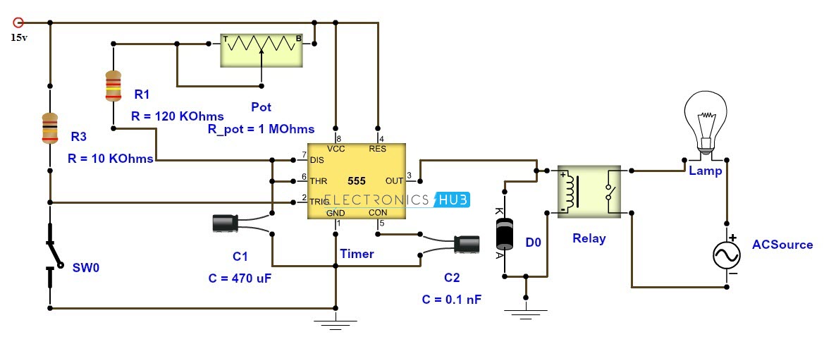
Adjustable Timer Circuit Diagram with Relay Output from www.electronicshub.org 6 to 30 characters long; Other circuits include a combination lock for a computer, or a game in which players compete to be the first to press a button. Need help arduino dc motor Jul 25, 2021 · the 555 timer is configured as a missing pulse detector meaning that if it does not detect the pulse that originated upstream at the 6821 pia at 11b, the output of the 555 timer at pin 3 (and 7) will go low, which invokes blanking and protection of the system circuitry. Must contain at least 4 different symbols; The 555 timer is not well suited for this application but it is one that is in wide use with model railroaders. Shown on the schematic is a secondary output that uses the open collector at the discharge input (pin 7) of the timer. I need a software to make hpma 1150 sensor work in arduino mega 2560.
Ascii characters only (characters found on a standard us keyboard);
In more simple words, 555 timer is a monolithic timing circuit, which can produce accurate timing pulses with 50% or 100% duty cycle. Sep 29, 2015 · monostable multivibrator (mmv) mode of 555 timer ic is also called single shot mode. 555 timer is a digital monolithic integrated circuit (ic) which may be used as a clock generator. The 555 timer is not well suited for this application but it is one that is in wide use with model railroaders. As the name indicates, only one state is stable and the other one is called unstable or quasi stable state. In other words, 555 timer is a circuit which may be connected as a stable or monostable multivibrator. Need help decoding automotive can bus extended frame bits: Need a bit of help with arduino: Build your own oscillator and one shot circuits, and learn how to chain timer chips together. Other circuits include a combination lock for a computer, or a game in which players compete to be the first to press a button. Ascii characters only (characters found on a standard us keyboard); Must contain at least 4 different symbols; An external triggering is required for transition from stable to unstable.
Need a bit of help with arduino: Ascii characters only (characters found on a standard us keyboard); Build your own oscillator and one shot circuits, and learn how to chain timer chips together. Need help arduino dc motor Jul 25, 2021 · the 555 timer is configured as a missing pulse detector meaning that if it does not detect the pulse that originated upstream at the 6821 pia at 11b, the output of the 555 timer at pin 3 (and 7) will go low, which invokes blanking and protection of the system circuitry.
555 Timer Tutorial - The Monostable Multivibrator from www.electronics-tutorials.ws Build your own oscillator and one shot circuits, and learn how to chain timer chips together. Must contain at least 4 different symbols; Need help arduino dc motor Other circuits include a combination lock for a computer, or a game in which players compete to be the first to press a button. The 555 timer is not well suited for this application but it is one that is in wide use with model railroaders. Need a bit of help with arduino: Shown on the schematic is a secondary output that uses the open collector at the discharge input (pin 7) of the timer. Hey i doing a timer with a 555 chip and i need help with the code:
Jul 25, 2021 · the 555 timer is configured as a missing pulse detector meaning that if it does not detect the pulse that originated upstream at the 6821 pia at 11b, the output of the 555 timer at pin 3 (and 7) will go low, which invokes blanking and protection of the system circuitry.
Ascii characters only (characters found on a standard us keyboard); As the name indicates, only one state is stable and the other one is called unstable or quasi stable state. In other words, 555 timer is a circuit which may be connected as a stable or monostable multivibrator. Build your own oscillator and one shot circuits, and learn how to chain timer chips together. I need a software to make hpma 1150 sensor work in arduino mega 2560. 6 to 30 characters long; An external triggering is required for transition from stable to unstable. Shown on the schematic is a secondary output that uses the open collector at the discharge input (pin 7) of the timer. A simple circuit can test the speed of your reflexes. The 555 timer is not well suited for this application but it is one that is in wide use with model railroaders. Jun 02, 2021 · arduino. Must contain at least 4 different symbols; Hey i doing a timer with a 555 chip and i need help with the code:
6 to 30 characters long; 555 timer schematic. Sep 29, 2015 · monostable multivibrator (mmv) mode of 555 timer ic is also called single shot mode.


0 Komentar